Vibeware: hardware is now NPC-accessible
Vibeware is hardware designed the way vibecoding builds software. You describe what you want, and AI models produce the design: the 3D model, the wiring, the firmware, the parts list. Then checks and simulations, written by the models too, catch what they get wrong.
TL;DR.
- Hypercustom simulation for anyone. Soon anyone will be able to build custom, LLM-written simulations for their own hardware: fit, electrics, heat, faults, and how the thing behaves. I did it twice, for two very different products, without being a hardware engineer.
- Early days. There are real unknowns, and it's still early, about where vibecoding was in early 2024. The models draft fluently and miss precise details. The checks, not the models, are what make it work.
What I built
Two kits, each with a workbench that shows everything on one page.
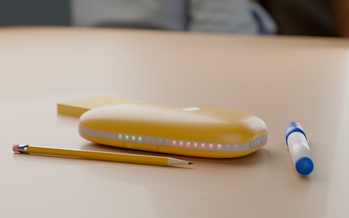
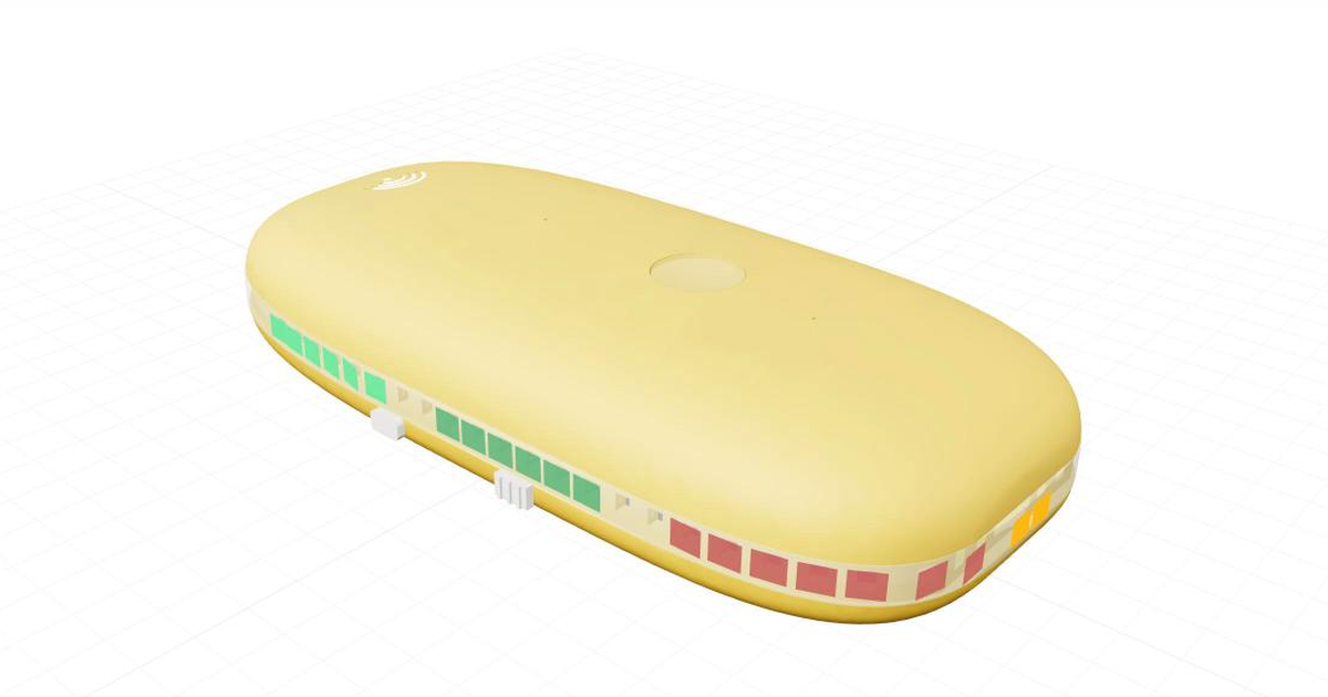
Goldfish
A pocket recorder where everyone in earshot controls how much of their own words is kept, and the record forgets on a schedule. A printed pebble, 18 cm and about 266 g, around a Radxa ZERO 3E. 66 modelled wires, 258 firmware tests.
VV-Bots
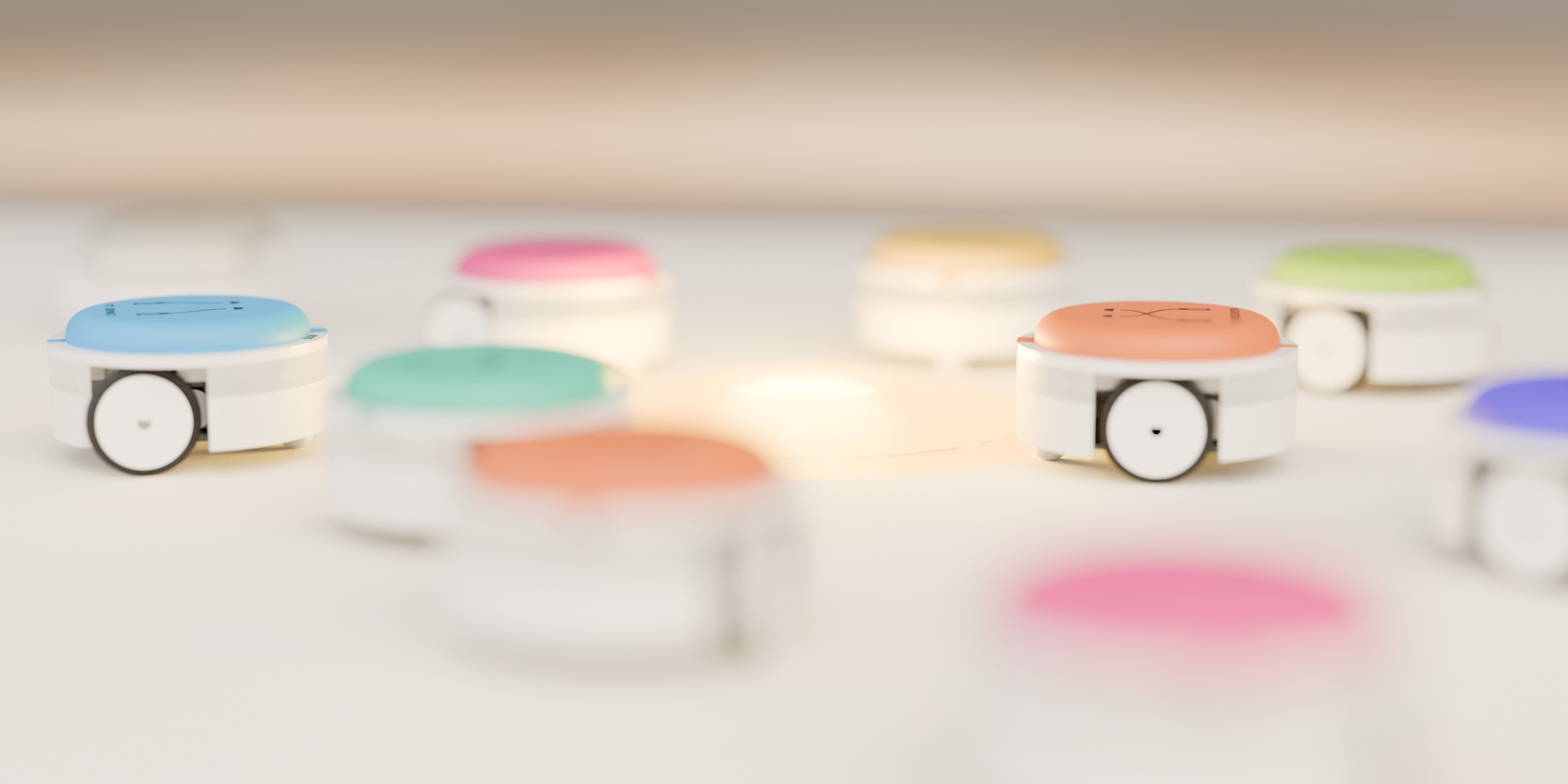
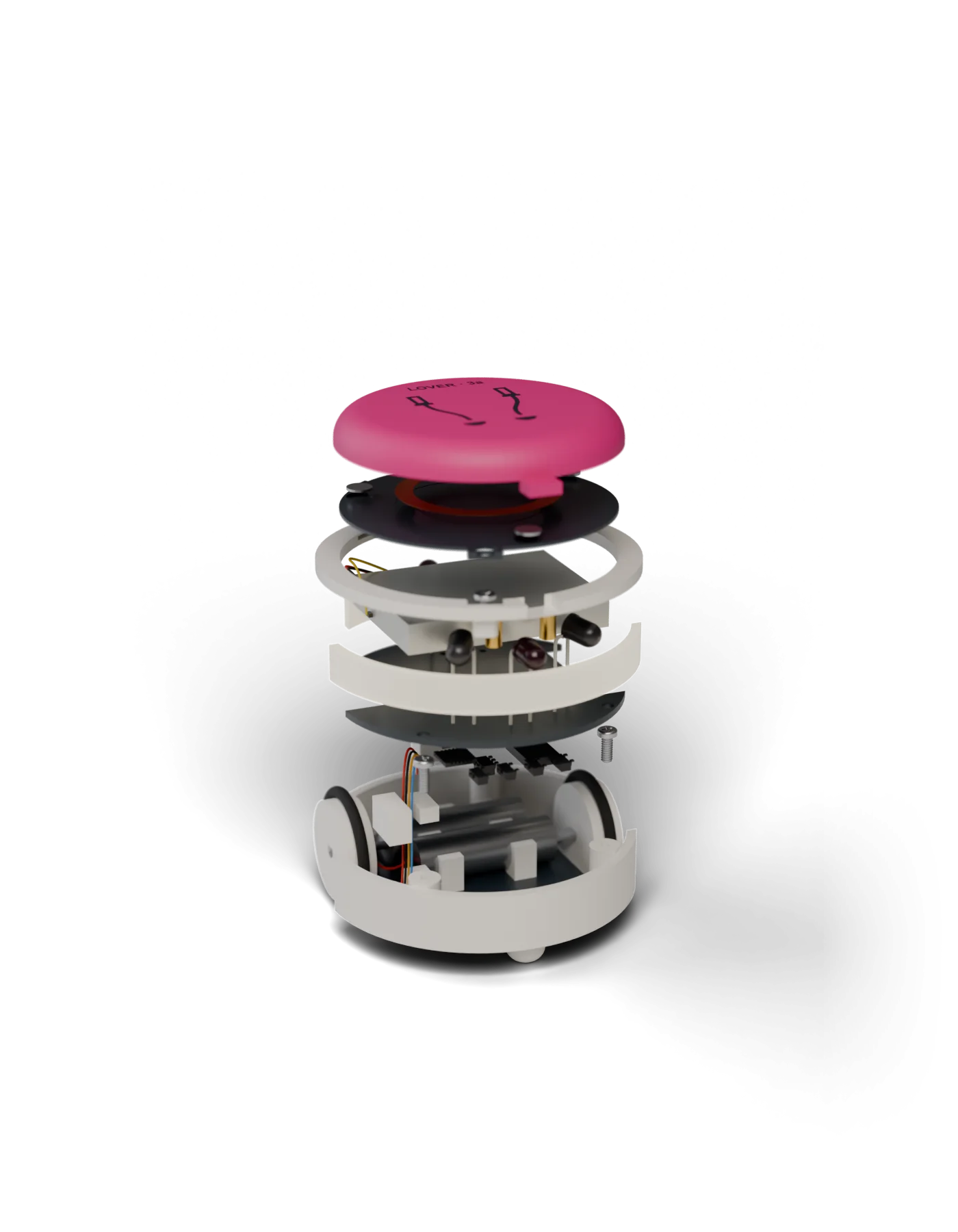
A swarm game: 24 palm-sized robots whose brain is the hat they wear, after Braitenberg's Vehicles. Rewritable NFC hats, drive-over light pads, a case that charges the set with the lid closed. The VV-Bots took two days from brief to this state: 34 CAD and electrical checks, 266 firmware tests.
The stack
All of it is code in one repo, generated from one spec file (dimensions, each with its source), and rebuilt on every change.
- MCAD: parametric parts in build123d (Python on the OpenCascade B-rep kernel). Exports STEP for vendors, STL for printing, glTF for the browser viewer.
- Mechanical design checks: mesh checks in trimesh. Interference and clearance, worst-case tolerance stack-ups, wall thickness, part-fits-the-print-bed, centre of mass over the contact points, and screwdriver reach to every fastener.
- Electrical: no schematic capture or PCB layout yet. A pin-level netlist written from datasheets gets an ERC (floating inputs, output contention, missing pull-ups, absolute maximums) and a DC operating-point solve (modified nodal analysis, in numpy) for the power tree, brown-out under peak load and standby drain. The battery is a time-stepped model from its open-circuit-voltage curve and internal resistance.
- Thermal: lumped-parameter RC networks, with masses taken from the CAD volumes and losses from the electrical model. They cover charging, play and fault cases (charger stuck on, case in the sun).
- Firmware: C for the bots' Cortex-M0+ (Puya PY32F003), unit-tested on the host against test vectors from the simulator's behaviour model, so the firmware and the simulator can't drift apart. Goldfish runs Python on a Radxa ZERO 3E, and its simulated meeting is replayed through the real firmware.
- Compliance: for VV-Bots, a requirements matrix against the toy route: EN 71-1, IEC 62115, ASTM F963 and RED for the NFC.
- BOM: a CSV with manufacturer part numbers, suppliers, price breaks and datasheet links.
- Renders: Blender, with the simulator's motion driving the robots in the films.
- Workflow: parallel agents, each in its own git worktree, merged and then gated by one validation script.
What worked
-
Design checks as a regression suite. Every requirement for geometry, wiring or heat became a check that runs on every build, the way DRC and ERC run in PCB tools. They caught:
- the hat's pogo pins interfering with the eye sensors;
- screws intruding into the cell;
- a 5 mm IR LED in the BOM, while the body had a 3 mm bore;
- an eye baseline too narrow for the swarm patterns to form.
-
Design intent stated up front. Each ask named the constraint:
- "easy to build and fix" (design for assembly and service) gave connectors and screws instead of solder;
- "toy route, 14+" set the applicable standards;
- "parts with EU stock" constrained the BOM.
-
Sourcing. Agents found alternates for parts that didn't fit or weren't stocked, and caught a part number for a USB-A connector listed as USB-C.
- Outputs. The STEP files, the BOM CSV and the netlist all come from the same source, so they agree.
What broke
Let's compare software memory management to temperature and physical tolerance error stacking. Software has garbage collectors and type checkers; hardware has nothing that manages heat or flags a stack-up for you.
- Heat. The first thermal model had the cells at 48 °C while charging in the closed case, over the 45 °C charge limit in the datasheet. The fix was hardware: an NTC on each charger's TS pin, a 4.7 V pocket rail to cut the linear chargers' dissipation, and a 1.8 V buck for the motors.
- Software is not a safety control. A firmware fault with stalled motors put the full cell voltage on them, and the windings reached 146 °C. IEC 62115's abnormal-operation tests fault the controls, so the limit had to be the 1.8 V motor rail.
- Tolerances stack. The worst-case stack of a bot's clearance in its pocket plus the pogo pin's tip needed 2.07 mm of contact on a 2.0 mm charge ring. Nothing flags that unless you write the check.
-
Agents can game the checks. Asked to make a check pass, a model may relax the limit instead of changing the design. My rules:
- every limit traces to a datasheet or a standard and never gets loosened;
- every check must fail once with an injected fault before it counts.
Where models are today
- Oct 2023. The best model solves 1.96% of real coding tasks on SWE-bench.
- Mar 2024. Devin solves 13.86%, on a quarter of the set.
- May 2026. Text2CAD-Bench: models "perform reasonably on basic geometry but degrade substantially on complex topology and advanced features."
- Sep 2026. CADWorld: the best CAD agent completes 17.5% of tasks, a human expert 87%.
So AI-for-CAD is roughly where AI-for-code was in early 2024. I found no benchmark yet for whether the parts actually fit once they're printed.
Playbook
- Keep one spec file as the single source of truth. Every dimension cites a datasheet or is marked "estimate".
- Trace every requirement to a check, and prove each check with an injected fault.
- Keep one behaviour model shared by the simulator and the firmware tests.
- Decide the design-for-X goals and the certification route first. They drive the BOM.
- Run independent workstreams in parallel on separate files, then rerun the full regression after each merge.
Unknowns
- Model vs measurement. Magnet pull, NFC range, fits and temperatures are all estimates until a prototype measures them. Neither kit has been built yet.
- Process variation. FDM parts come out a tenth or two of a millimetre off and plastics shrink, but the CAD assumes nominal sizes.
- Test coverage. A design can pass every check and still fail in a way nobody wrote a check for.
- Certification. Pre-compliance can be modelled, but the safety and radio tests happen in an accredited lab, and their cost and outcome are unknown until you book one.
- Supply. Parts go out of stock or reach end of life. Several in these builds are single-sourced or still need a confirmed supplier.
What's next
Build a first prototype of each and bench-test it: bring-up, then measure currents, temperatures, magnet pull, NFC range and fits, and replace the estimates with those numbers. Then simulated users (builders, players, auditors) as a design loop.